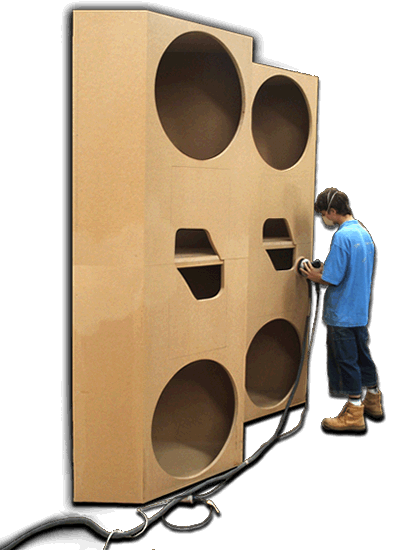
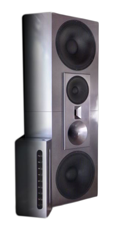
This system shown in these pages is an example of a commissioned audiophile Opal system with 27 inch bass speakers. Yes, you read correctly, four 27 inch bass speakers!
With a passion for pipe organ music our client was aiming to relive a childhood experience and to bring back fond memories and feelings from a special time in his life. The challenge was great; not only for us to find a way to provide this experience, but also for our client who needed to extend the limits of his imagination and work with us to make this happen.
As large pipe organ bass note sub-harmonics can reach below 16.4Hz, finding a way to faithfully reproduce the depths of notes created on these magnificent instruments was our first challenge. Our second challenge was to keep the cabinet design within the limits of the space provided.
Our resolution was a design to fit within room corners, and this surprisingly has minimum effect on consuming living space. The system height is designed to fit floor to ceiling 2.5 meters, 8ft.
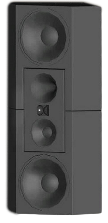
Each speaker structure is made up with 3 cabinets. Two bass boxes: one inverted on top of the other and a 3-way centre box that fits within the 2 bass boxes. The centre box can be rotated 180deg, allowing the mid horn to be at the correct listening height when listening from a seated position.
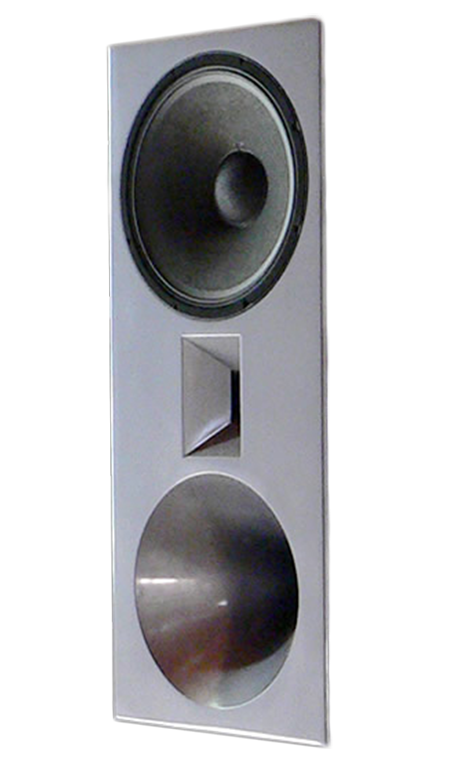
These particular custom cabinets were painted with Mercedes metallic-grey auto duco however custom systems can be designed in a range of finishes to suit the client including high grade timber veneers.
This particular system was reviewed by Stephen Dawson from Australian Hi Fi Magazine in the March/April 2007 edition.
Custom Opal systems can be made in a range of sizes and finishes and to suit any environment, application and architectural design.
Custom Opal systems are available from AUD 70,000. Sales enquiries please email us.
The amplifiers for the cone speakers (bass and lower voice) are in class AB which enables 100 Watts of power to be achieved. However the amplifiers for the upper voice 2in compression driver and tweeter are in class A which limits power to 40 Watts.
The efficiency of the compression driver and tweeter is approx 100 times greater than the lower frequency cone speakers and only requires 1/100 the power to achieve the same level.
The high frequency drivers are very sensitive to detail and it is essential for the amplifiers to be as close to class A as possible to achieve the lowest distortion figurers.
The 4 four way active crossover is at the top of the cabinet and the controls easily accessible. The crossover frequencies are calibrated to achieve the best performance from the speakers.
The level controls of the crossover are calibrated for free field which means zero room reverberation. The controls can be easily re-adjusted to give the best performance to suit the room environment and music.
The crossover is Linkwitz-Riley 4th order time aligned.
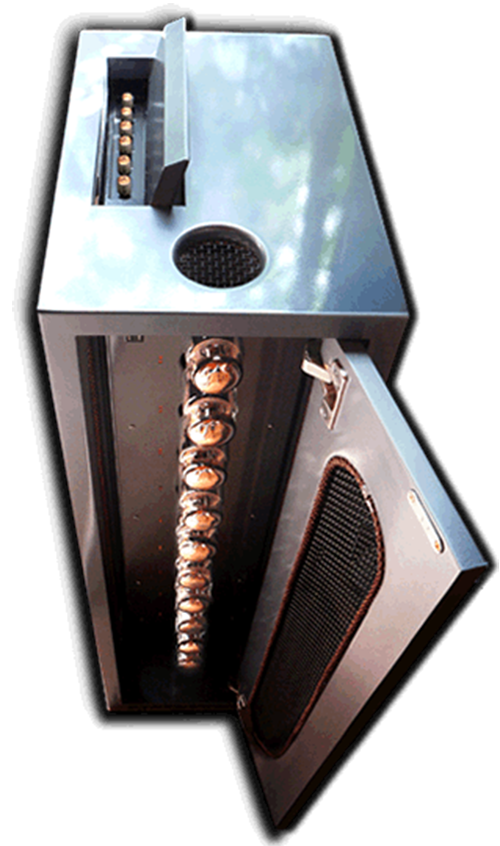
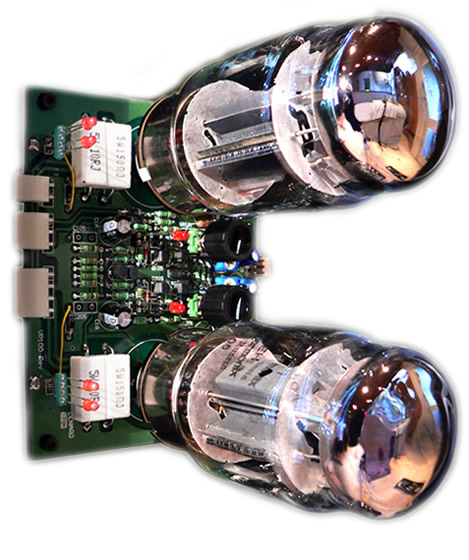
Each 100 Watt amplifier is a separate module and can be changed easily if required. Each valve bias (temperature) can be easily externally adjusted. New valves take approx two weeks to stabilise.
The two red LEDs (light emitting diodes) in front of each valve in this photo are a comparator. When both LEDs are at the same light intensity the valve bias is correct. The amplifier modules are vertically aligned in the cabinet and therefore the LEDs are in the vertical position as in the pic on the right.
The middle LEDs in-between the valves indicate by flashing if a valve has failed and needs to be replaced. Replacement valves are readily available and each system is provided with spare valves.
The driver circuitry is solid-state which is absolutely silent and non-microphonic. This is essential for very efficient active speaker systems that use compression drivers. The microphonic and thermionic noise (hiss) generated by small driver valves would be audible and intolerable. The unique sound quality of valve amplifiers is created by the output stage (power valves and output transformer). This unique quality is not created by using small pre amplifier valves.
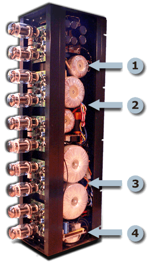
The power supply is mounted on the right side of the chassis.
1
The small top toroid power transformer (+-20V and +-100V) is for the electronic crossover and driver circuits of KT88 output valves.
2
The two medium toroid for the 12.6V DC valve heater supply of 8 Amperes.
The DC heater polarity + – is reversed each time the amplifier is turned on.
This ensures valve filaments and cables are free from electrolytic deterioration.
3
The two large toroid transformers create the 600V HT supply.
The HT supply is constructed from 3 X 200V supplies in series.
This enables a 400V supply for the 2 high frequency amplifiers in class A push pull.
4
The power turn on management system is at the bottom of the chassis.
All power transformers are toroid, to insure zero magnetic interference, and are also electrostaticly shielded.
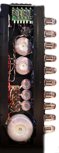
The output transformers and Electronic crossover are mounted on the left side of the chassis. All output transformers are toroid and are of greater frequency range than required for each defined bandwidth. All output transformers are also frequency specified flat at 200W full power.
1
This shows the 4 way, Electronic crossover.
2
Hi-frequency small transformer (500Hz – 50KHz) is at the top.
3
The two medium output transformers for upper and lower mid frequencies (40Hz – 16KHz).
4
The 3 small toroid chokes mounted vertically above the large bass output toroid transformer are for filtering the 600V HT supply.
5
The large bass toroid transformer is capable of (5Hz – 10KHz) at base of the chassis.
Questions are often asked about valve amplifier class Push pull Single ended A AB B.
Single ended refers to the 1 single output valve in small cheap radios and radiograms that were made before 1960. A single output valve is only capable of small power and produces a non-synchronous second harmonic distortion. Some audiophiles claim this distortion has spiritual qualities similar to magical crystals and crop circles.
Class A single ended refers to the 1 output valve needing to be at maximum quiescent temperature to obtain the small power available. This is similar to a one legged person riding a one pedal push bike. As it is not possible to pull up and push down on the pedal with identical energy, the output is non-synchronous.
Push pull refers to two output valves, similar to a 2 cylinder auto engine, or a push bike with 2 pedals. Push Pull produces 4 times the power than single ended and has minimal distortion, due to being fully synchronous balanced. The correct way to make valve amplifiers, and push bikes.
Push Pull two output valves is naturally efficient with minimum distortion. There is no scientific evidence that push pull achieves lower distortion by running the output valves at the maximum allowable temperature. However greater academic linearity is achieved by running the valves, with lower voltage and higher current, resulting in less power, insuring zero distortion. Sometimes referred to as class A push pull.
Class AB refers to push pull for audio application. The valves are run at medium temperature insuring there is an overlap where one valve takes over from the other for each half of the wave form. Increasing the temperature increases the overlap, referred to as Class AB1 and AB2. The latter has the least overlap.
Class B refers to push pull but not for audio application. In radio transmitters the valves are run at the minimum quiescent temperature (zero overlap) to obtain maximum power. If class B were used for audio there would be a gap between the top and bottom half of the music signal, which would be clearly audible as 3rd harmonic distortion.
Many of todays audiophile valve amplifiers are constructed similarly to the original designs that were made in the 1950s and 1960s. This is done for romantic nostalgia similar to grandfather clocks. However advances in modern technology and transformer design (toroid) has since enabled valve amplifiers to be vastly improved as in the Lenard Audio designs.
From the original 2D concept the architectural CAD drawings are created and a computer graphic of the final outcome as in the picture at the right. From here the plans are taken to the workshop where the actual construction will commence.

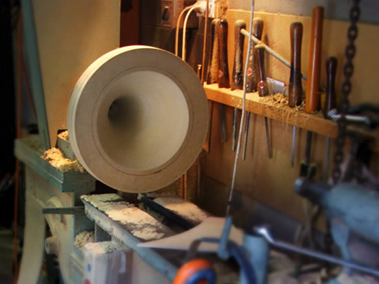
During the construction phase, skilled craftsmen are engaged to bring to life the plans. The mid-range horns for the 2in compression drivers are turned from a solid block of MDF. Small horns are also made for the hi-frequency slot radiators, to improve acoustical directivity.
The mid and tweeter horns are then permanently fitted within the centre box baffle. This procedure insures that secondary acoustical resonances are zero, and only the music is heard.
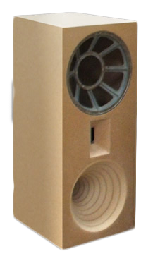
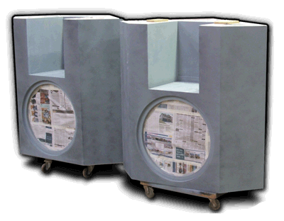
The sub bass sections are prepared for their intial undercoat of paint. The finish is chosen by the client.
The three way centre box contains the original 1970s classic JBL components These components are now collectors items, and were made when engineering craftsmanship was at its height. The application of these components, honours the earlier engineers who’s life passion was dedicated to excellence.
The musical performance of these original components is outstanding. The design and impedance of these components was created for achieving the best performance with valve amplification, which was the standard for monitoring till late 1970.
Most Opals are assembled with modern high quality speaker components. However the opportunity to receive a commission to create a system with original JBL classic components is a dream come true. There are many variations of how Opal systems can be configured, and each application will give varying results which are tailored to the clients musical interests and of course the listening environment.
This system is capable of delivering the full dynamic experience of a symphony orchestra, as though it is actually present, including a 16Hz note of a 64ft organ pipe.
Comparisons of smaller systems can be argued. However the laws of physics govern us all; there is simply no right or wrong. But ‘sad to say’ for those who’s unshakeable beliefs are attached to the latest model numbers of small audiophile 2-way speaker systems with magical cables, the musical experience of a hand crafted large 4-way active Opal system with classic 70s speaker components, will have no meaning. They simply won’t understand the whole thing, not unlike trying to sell mobile phone deals to technophobes.
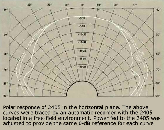
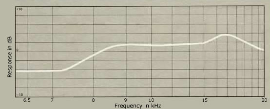
JBL 2405 slot radiator 6kHz – 20kHz
The 2405 is designed for use as the ultra-high frequency driver in a wide range, multi-element loudspeaker system. It features a unique combination of extended frequency response, high efficiency and wide dispersion pattern.
Frequency response extends smoothly from 6500 Hz to beyond the range of human hearing. A unique diffraction horn provides horizontal dispersion that is greater than 90 degrees at 16 kHz and 65 degrees at 20 kHz – far wider than conventional direct radiating loudspeakers of comparable efficiency, regardless of their size. Vertical dispersion pattern is 30 degrees at 16 kHz and 25 degrees at 20 kHz. Dispersion pattern measurements are determined from the points where level is 6dB down from the on-axis value using "-octave bands of pink noise as the signal source. For a given power input, the 2405 produces an exceptionally high acoustic output, converting 1-Watt input into a sound pressure level of 105 dB at a distance of one meter. At typical monitoring levels, such efficiency allows the 2405 to recreate intense high frequency onsets and transients with outstanding clarity and accuracy.
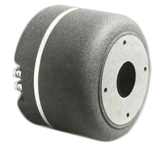
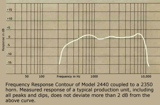
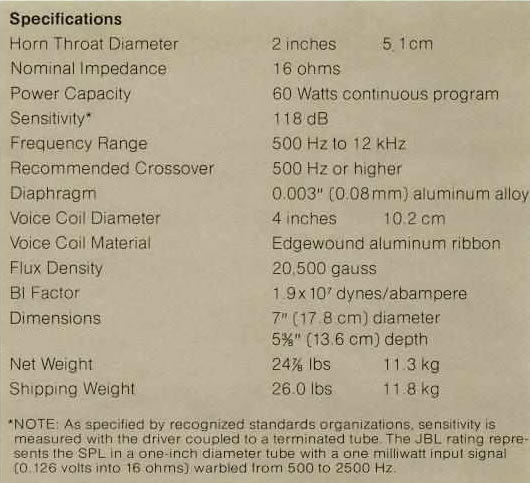
JBL 2440 2 inch compression driver and horn 800Hz – 6kHz.
Model 2440 is a massive professional quality compression driver built to typical JBL standards of precision. It has a four inch voice coil, and an Alnico V magnetic structure weighing more than 23 pounds. It can take the most explosive transients in stride, and reproduce them at thunderous levels with flawless accuracy.
Mathematically determined phasing plugs are machined concentric exponential horns to eliminate phase cancellations. Magnetic assemblies are cast and machined to hold tolerances considered impractical by industry standards. Diaphragms of aluminum alloy are pneumatically drawn to shape to eliminate crystal stresses that cause fatigue. After manufacture, the frequency response of each driver is tested and a peak or dip in response is rejected.
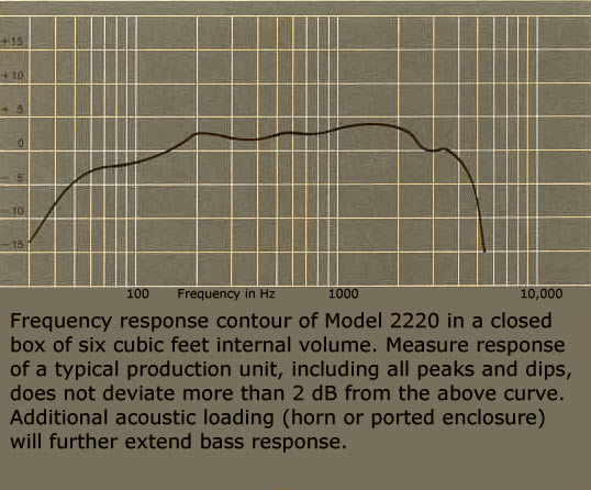
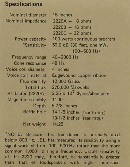
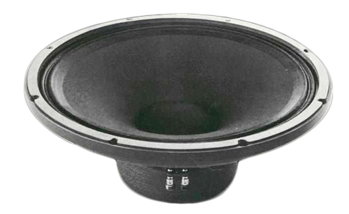
JBL 2220 15 inch speaker 100Hz – 800Hz
Model 2220 is the professional quality low frequency transducer with the greatest possible conversion efficiency. Its combination of highly efficient magnetic structure and relatively light cone assembly ideally suit the 2220 for use a bass horn driver, or in arrays of multiple low frequency units. It will also deliver good results in a ported enclosure, but with reduced deep bass response. The unit is offered in 8, 16 and 32 ohm impedances.
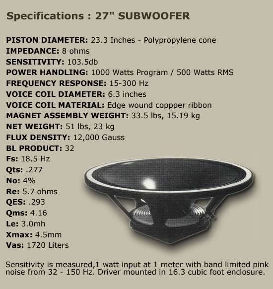
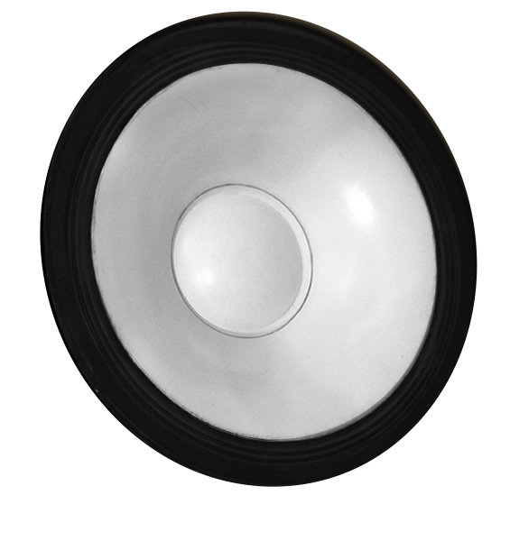
27 inch speaker 16Hz -100Hz
Large diameter speakers improve the coupling efficiency to the air at low frequencies and can easily reproduce the lowest note from a 64ft organ pipe 16Hz as sounding real. The 27in were made by Rick Randell 1980s and are capable of producing extreme sound levels which is not the purpose for this application The 27in bass speakers are very efficient 102db/mW, and they achieve the maximum level required with 10 Watts collectively. However 400W is available.
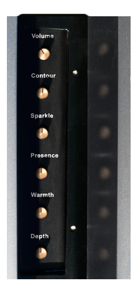
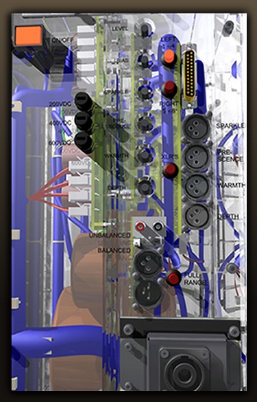
The controls for the system are easily accessible in a recessed section, at the top of each amplifier cabinet. Levels are independently controlled. Calibration of the system is for the acoustic environment and is for the enjoyment of performance. This is personal, and simple to perform, and most of all, enjoyable.
Volume
Master gain control
Sparkle
40 Watt class A amplifierfor the tweeter (harmonics)
Presence
40 Watt class A amplifierfor the compression driver (upper voice)
Warmth
100 Watt amplifierfor the15 inch speaker (lower voice)
Depth
2 x 100 Watt amps for the 2 x 27 inch speakers (sub-bass)
Contour
High frequency enhance control compensates for large rooms,
air attenuation and cinema screen.
Flat anti-clockwise, clockwise to enhance.
The Opal is built in 4-way, electronic crossover divides the frequency spectrum into four separate bands. These bands are then sent independently to the five power amplifiers which drive each speaker driver.
Stereo RCA or XLR Balanced
XLRs Male Balanced switched
XLRs Female Balanced switched
Bass sections of the Opals are slaved
Mains power
IEC 110V / 240V dedicated
Power is controlled for speaker protection
Manual and remote turn on/off
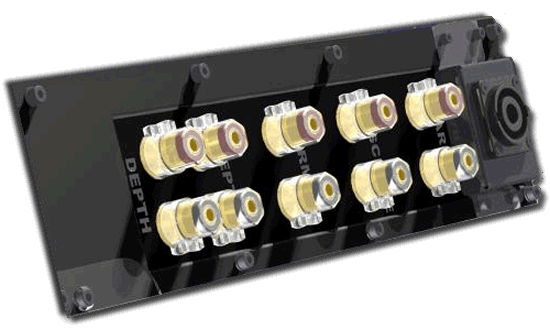
Located On the rear of each cabinet are gold plated binding posts. These will accept either bare wire or banana plugs and power each speaker independently. For the professional choice there is a speakon NL8 socket which makes cable management simple.
The industry-standard speakON connector option reduces cable management issues and provides a single connector that locks into place.